
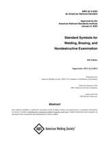

AWS A2.4:2020 Standard Symbols for Welding, Brazing, and Nondestructive Examination
AWS A2.4:2020 8th Edition standardizes welding, brazing and nondestructive examination symbols for engineering drawings, fabrication and inspection.
Wrong edition, wrong file, or a file that won’t open? We replace or refund — contact us within 7 days.
Buy now is for one copy. Buying for a team? Get a quote
About this publication
Product Description
AWS A2.4:2020, Standard Symbols for Welding, Brazing, and Nondestructive Examination, establishes the standardized graphical language used to communicate welding, brazing and nondestructive examination requirements between designers, engineers, fabricators, welders, inspectors and other personnel.
The standard provides rules for constructing and interpreting welding and examination symbols used on engineering drawings. It establishes how information such as weld type, location, size, length, extent, contour and examination requirements is placed on or around the symbol.
Current 8th Edition
AWS A2.4:2020 is the 8th Edition of the standard and supersedes AWS A2.4:2012.
The American Welding Society continues to list the 2020 edition as the current A2.4 publication. Current ANSI catalog records identify it as the most recent edition and do not list amendments or corrections.
Purpose of AWS A2.4
Welding symbols provide a concise method for conveying joining requirements without relying on lengthy written instructions on engineering drawings.
The standard is intended to improve communication from the designer to fabrication and inspection personnel by establishing consistent conventions for the location and interpretation of welding, brazing and nondestructive examination information.
What the Standard Does Not Do
AWS A2.4 does not establish welding tolerances, engineering design requirements or acceptance criteria for completed welds.
Instead, it establishes the graphical system used to communicate those requirements when they have been determined by the applicable design, code, specification or contract document.
Basic Welding Symbols
The standard explains the distinction between a weld symbol and the complete welding symbol.
The weld symbol identifies the type of weld, while the complete welding symbol can also include the reference line, arrow, tail, dimensions and supplementary information needed to describe the required joint.
Reference Line and Arrow
The reference line and arrow form the foundation of the AWS welding-symbol system.
Placement of the weld symbol relative to the reference line indicates whether welding is required on the arrow side, other side or both sides of the joint.
Tail of the Welding Symbol
The tail can be used to communicate supplementary information such as welding processes, specifications, procedures or other referenced requirements.
Not every welding symbol requires a tail; its use depends on whether additional information is necessary.
Supplementary Symbols
AWS A2.4 includes supplementary symbols used with basic weld symbols to convey additional requirements.
These include symbols addressing field welding, weld-all-around requirements, contour, melt-through and other conditions that cannot be communicated by the basic weld symbol alone.
Joint Types
The standard identifies common joint configurations used in welded construction and provides conventions for relating the welding symbol to the physical joint.
Understanding the joint type is important because the symbol communicates the required weld, while the drawing and joint geometry establish where that weld is applied.
General Provisions for Welding Symbols
The standard provides detailed rules covering arrow location, weld location, symbol orientation, breaks in the arrow, combination weld symbols, multiple arrows and multiple reference lines.
It also addresses extent of welding, the weld-all-around symbol, contour symbols, melt-through, U.S. Customary and SI units, tolerances and changes in joint geometry during welding.
Groove Weld Symbols
A substantial portion of AWS A2.4 addresses groove welds.
The standard explains how groove type, groove depth, weld size, groove angle, root opening, weld length, contour and other information are indicated on the welding symbol.
Groove Weld Configurations
The standard includes symbol conventions for common groove configurations and detailed examples showing how dimensional information is associated with the symbol.
It also addresses backing welds, joints with backing or spacers, consumable inserts, backgouging, seal welds, skewed joints and combination groove welds.
Flare Groove Welds — Expanded 2020 Guidance
The 2020 edition adds more detailed guidance for flare groove welds.
This change improves the representation and interpretation of flare-bevel and flare-V-groove welds commonly encountered with rounded or curved member edges.
Combination Groove Weld Symbols
The 8th Edition introduces an important change permitting a combination groove weld symbol to designate two different edge shapes.
One groove symbol can be shown in a reversed orientation when necessary to represent the actual configuration of the joint, such as a combination involving flare-bevel and bevel groove conditions.
Multiple Subreference Lines
The 2020 edition permits multiple subreference lines where a groove weld extends around a joint and there is no clear point at which one joint configuration changes to another.
This provides designers with a clearer method for communicating complex continuous weld configurations.
Fillet Weld Symbols
Clause 8 addresses fillet welds, one of the most frequently used weld types in structural and fabricated assemblies.
The standard explains notation for fillet weld size, length, intermittent welds, welds in holes and slots, contours and skewed joints.
Plug Weld Symbols
Clause 9 establishes symbol conventions for plug welds, including weld size, countersink angle, depth of filling, spacing, quantity and contour.
The 2020 edition changes the treatment of the diameter symbol. The diameter symbol is no longer an integral part of the plug weld symbol itself, although it is still used when designating the plug dimension.
Slot Weld Symbols
Clause 10 addresses slot weld width, length, countersink angle, depth of filling, spacing, number of welds, orientation and contour.
These requirements provide a standardized method for communicating slot weld geometry without forcing designers to replace symbolic information with extensive written notes.
Spot Weld Symbols
Clause 11 provides symbol requirements for spot welds, including size, spacing, number, extent and contour.
The 2020 edition changes the method for communicating spot-weld size or strength. A dimension placed to the left of the symbol now indicates weld size only; strength information must be communicated separately, such as through information in the tail.
Seam Weld Symbols
Clause 12 addresses seam welds and provides conventions for weld size, length, intermittent seam weld dimensions, quantity, orientation and contour.
As with spot welds, the 2020 edition revises how size and strength information is communicated.
Edge Weld Symbols
Clause 13 covers edge welds.
The provisions address edge weld size, single- and double-edge welds, complete joint penetration conditions, joints involving more than two members, weld length and intermittent edge welding.
Stud Weld Symbols
Clause 14 provides symbol conventions for stud welding.
Requirements include side significance, dimensional placement, stud size, stud spacing, number of studs and the location of first and last stud welds.
Surfacing Weld Symbols
Clause 15 establishes symbols for surfacing welds.
The standard addresses deposited thickness, extent, location, orientation, surfacing over previous welds and use of surfacing to adjust component dimensions.
Brazing Symbols
Clause 16 applies the AWS symbolic system to brazing.
Brazing generally uses the same symbol conventions used for welding, supplemented by provisions applicable specifically to brazed joints.
Scarf Symbol
The brazing provisions include use of the scarf symbol where applicable.
This allows brazing-specific joint information to be communicated while maintaining consistency with the broader AWS symbolic system.
Nondestructive Examination Symbols
Clause 17 establishes symbols used to communicate nondestructive examination, or NDE, requirements on drawings.
The symbols can identify examination method, location, extent, orientation, frequency or number of examinations and other information necessary to define the required inspection.
Expanded NDE Clause — 2020 Revision
The nondestructive examination symbols clause was substantially rewritten and expanded for the 2020 edition.
The revised provisions address examination method letter designations, supplementary symbols, location significance, multiple reference lines, coordination with welding symbols, U.S. Customary and SI units, specifications and codes, examination extent and examination of defined areas.
Examination Method Letter Designations
The standard includes a table of standardized letter designations for nondestructive examination methods.
These letter designations allow the required examination process to be identified directly within the symbolic system while detailed procedural and acceptance requirements remain governed by the referenced examination standard or code.
Welding and NDE Symbols Together
AWS A2.4 provides conventions for combining welding symbols and nondestructive examination symbols where both fabrication and inspection requirements need to be communicated on the same drawing.
This helps engineers distinguish between requirements for creating the joint and requirements for examining the completed work.
Contour and Finish Symbols — 2020 Change
The 2020 edition changes the interpretation of contour symbols when no specific finishing method is designated.
The required contour can now be achieved by an appropriate method rather than being assumed to result from welding alone. The flat contour symbol is limited to fillet welds, while the flush contour designation is used for other applicable welds such as groove, plug and slot welds.
Flash and Upset Welding Symbols
Dedicated flash and upset welding symbols are no longer supported in the 2020 edition.
Where such process information is necessary, AWS recommends use of the reference line and arrow with the applicable process designation communicated through the tail or other appropriate notation.
Figure Numbering
The 2020 edition renumbers figures so their identifiers correspond more clearly with the clauses in which they are referenced.
This makes the numerous graphical examples easier to locate and connect with the associated technical requirements.
Normative Annex A
Normative Annex A contains tables supporting application of the standard.
These include joint type designators, letter designations for welding and allied processes, cross-references, application-mode suffixes and examination-method letter designations.
Standard Symbol Design
Informative Annexes B and C provide dimensional guidance for construction of standard symbols in U.S. Customary and SI units.
These annexes are particularly useful when preparing technical drawings, CAD standards or standardized drafting libraries.
Commentary
Informative Annex D provides commentary on AWS A2.4.
The commentary offers additional explanation and examples addressing application of the symbolic system without becoming mandatory requirements of the standard.
Welding Symbol Chart
Informative Annex E contains a welding symbol chart summarizing commonly used symbols.
AWS also publishes separate A2.1 desk and wall charts designed to complement A2.4 for shop, classroom and drafting use.
ISO 2553 Comparison
Informative Annex F addresses ISO 2553 welding symbols and compares selected ISO and AWS symbol conventions.
This is useful for organizations working with drawings, projects or suppliers using both U.S. and international symbolic systems.
Relationship to AWS B1.10
The NDE symbol provisions are coordinated with AWS B1.10M/B1.10, Guide for the Nondestructive Examination of Welds.
A2.4 establishes how examination requirements are symbolically communicated, while the examination guide and applicable inspection codes provide technical information about the NDE methods themselves.
Relationship to AWS A3.0
AWS A3.0 establishes standard welding terminology and definitions.
A2.4 complements that terminology standard by providing the graphical language used to communicate welding and allied-process requirements on drawings.
Relationship to AWS D1 Welding Codes
AWS D1 structural welding codes frequently rely on engineering drawings and welding symbols to communicate joint requirements.
A2.4 provides the standard symbolic language, while the applicable D1 code establishes design, qualification, fabrication, inspection and acceptance requirements.
2020 Edition Major Changes
- expanded guidance for flare groove welds;
- diameter symbol removed as an integral part of the plug weld symbol;
- revised contour and postweld finishing conventions;
- flat contour symbol limited to fillet welds;
- flush contour designation used for other applicable welds;
- new combination groove weld symbol treatment for different edge shapes;
- multiple subreference lines permitted for complex groove weld configurations;
- revised size and strength notation for spot welds;
- revised size and strength notation for seam welds;
- flash and upset welding symbols removed;
- figures renumbered to correspond with their clauses;
- nondestructive examination symbols clause rewritten and expanded.
Who Should Use AWS A2.4:2020
- welding engineers;
- structural engineers;
- mechanical engineers;
- designers and detailers;
- drafting and CAD professionals;
- welding inspectors;
- AWS Certified Welding Inspectors;
- welding supervisors;
- fabricators and manufacturers;
- welders and brazers;
- nondestructive examination personnel;
- quality assurance and quality control personnel;
- technical educators and students;
- engineering and fabrication firms.
Product Features
- current 8th Edition of AWS A2.4;
- ANSI approved;
- 166 pages in current distribution metadata;
- covers welding, brazing and NDE symbols;
- covers basic welding-symbol construction;
- covers joint types and symbol placement;
- covers groove weld symbols;
- covers fillet weld symbols;
- covers plug and slot weld symbols;
- covers spot and seam weld symbols;
- covers edge and stud weld symbols;
- covers surfacing weld symbols;
- includes brazing symbol provisions;
- includes expanded NDE symbol requirements;
- includes U.S. Customary and SI symbol guidance;
- includes normative symbol-designation tables;
- includes standard symbol construction guidance;
- includes a welding symbol chart;
- includes AWS and ISO 2553 symbol comparisons;
- supersedes AWS A2.4:2012.
Product Details
- Standard: AWS A2.4:2020
- Title: Standard Symbols for Welding, Brazing, and Nondestructive Examination
- Edition: 8th Edition
- Publisher: American Welding Society
- Publication Year: 2020
- ANSI Approval Date: January 9, 2020
- Print ISBN: 978-1-64322-091-8
- PDF ISBN: 978-1-64322-092-5
- Page Count: 166
- AWS Order Code: A2.4
- Previous Edition: AWS A2.4:2012
- Prepared By: AWS A2 Committee on Definitions and Symbols
- Language: English
- Publication Type: Welding Symbols Standard
Edition Status Note
AWS A2.4:2020 remains the current edition as of October 2026. AWS continues to identify the 2020 publication as its current Standard Symbols for Welding, Brazing, and Nondestructive Examination, and current ANSI records list no amendments or corrections. The 2020 edition supersedes AWS A2.4:2012.