
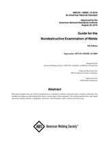

AWS B1.10M/B1.10:2016 Guide for the Nondestructive Examination of Welds
AWS B1.10M/B1.10:2016 5th Edition guide covers VT, PT, MT, RT, UT, eddy current and leak testing for nondestructive weld examination.
Wrong edition, wrong file, or a file that won’t open? We replace or refund — contact us within 7 days.
Buy now is for one copy. Buying for a team? Get a quote
About this publication
Product Description
AWS B1.10M/B1.10:2016, Guide for the Nondestructive Examination of Welds, Fifth Edition, provides a practical overview of the principal nondestructive examination methods used to evaluate welds and welded materials without destroying their usefulness.
Prepared by the American Welding Society B1 Committee on Methods of Inspection, the guide helps inspectors, engineers, quality personnel and welding professionals understand which NDE methods are generally best suited for detecting particular types of weld discontinuities.
Current Fifth Edition
The 2016 Fifth Edition remains the current AWS B1.10 publication as of October 2026 and supersedes AWS B1.10M/B1.10:2009.
The American National Standards Institute approved the Fifth Edition on August 29, 2016.
Purpose of the Guide
AWS states that the purpose of B1.10 is to provide an overview of the more common nondestructive examination methods without unnecessary detail and to assist users in selecting the method generally best suited to a particular weld examination.
The guide is intended as a simple but reliable source of general information rather than a complete textbook covering every aspect of nondestructive examination.
Nondestructive Examination Methods Covered
AWS B1.10 covers seven principal examination methods:
- Visual Examination — VT;
- Liquid Penetrant Examination — PT;
- Magnetic Particle Examination — MT;
- Radiographic Examination — RT;
- Ultrasonic Examination — UT;
- Electromagnetic or Eddy Current Examination — ET;
- Leak Testing — LT.
Selecting an NDE Method
No single nondestructive examination method is best for every weld, material or discontinuity.
AWS identifies several principal factors that should be considered when selecting an examination method, including the method's advantages and limitations, the anticipated type and size of discontinuity, applicable acceptance standards and cost.
Acceptance Criteria Are Not Included
AWS B1.10 does not establish universal weld acceptance criteria.
The guide states that requirements for nondestructive examination and the applicable acceptance criteria should be specified in procurement documents before contracts are awarded.
A weld can contain a discontinuity and still be acceptable when its type, size and distribution remain within the limits established by the governing construction code or specification.
Examination Procedures
The guide emphasizes that NDE methods should be performed according to an approved written procedure available to the technician performing the examination.
A documented procedure supports consistent preparation, examination, interpretation and compliance with the applicable code or specification.
NDE Symbols
AWS B1.10 includes information concerning nondestructive examination symbols and abbreviations.
These symbols provide a standardized method for communicating examination requirements on engineering drawings and related technical documents.
Clause 4 — Weld Discontinuities
Clause 4 discusses common weld and base-metal discontinuities that can be encountered during fabrication and inspection.
Understanding the nature, orientation and location of a discontinuity is important because different NDE methods have different abilities to detect particular conditions.
Porosity
Porosity consists of cavities associated with gas entrapment in weld metal.
The guide discusses porosity as a common weld discontinuity and relates its detection to the capabilities of applicable visual, radiographic and other examination methods.
Inclusions
Inclusions are foreign solid material trapped within weld metal or at fusion boundaries.
Depending on location, orientation and size, suitable volumetric examination methods can be required to identify inclusions that are not visible at the surface.
Incomplete Fusion
Incomplete fusion occurs when fusion does not occur between weld metal and base metal or between adjacent weld beads.
Its detectability depends heavily on the orientation of the discontinuity relative to the examination technique.
Incomplete Joint Penetration
Incomplete joint penetration occurs when weld metal does not extend through the joint as required by the intended weld configuration.
The guide includes this condition among the discontinuities considered when selecting an appropriate examination technique.
Undercut
Undercut is a groove melted into the base metal adjacent to a weld toe or root and left unfilled by weld metal.
Accessible undercut can generally be evaluated visually, while dimensional acceptance limits are established by the governing code or specification.
Underfill and Overlap
The guide covers both underfill and overlap as weld surface conditions relevant to inspection.
Visual examination is commonly useful for detecting these accessible surface discontinuities.
Laminations and Delaminations
Base materials can contain laminations or experience delamination.
AWS notes that examination-method selection must consider discontinuity orientation. Radiography, for example, can have difficulty detecting planar discontinuities oriented parallel to a plate surface, while properly oriented ultrasonic examination can be more effective.
Seams and Laps
The guide discusses seams and laps associated with base material.
Recognizing these conditions helps inspectors distinguish material-manufacturing discontinuities from discontinuities produced directly by welding.
Lamellar Tears
Lamellar tearing is included among the discontinuities discussed in Clause 4.
Its orientation and location within or adjacent to a welded joint influence which NDE method is capable of reliably detecting it.
Cracks
Cracks receive dedicated treatment because their orientation, location and morphology strongly influence examination-method effectiveness.
The Fifth Edition includes an expanded illustration identifying different crack types and locations associated with welded joints.
Concavity, Convexity and Weld Reinforcement
The discontinuity section also addresses weld contour conditions including concavity, convexity and weld reinforcement.
These characteristics are commonly evaluated through visual examination and dimensional measurement, although their acceptability is determined by the applicable governing standard.
Visual Examination — VT
Visual examination is generally the simplest and least expensive NDE method.
VT can identify visible surface discontinuities, dimensional conditions, weld profile and workmanship issues where the examination surface is accessible.
Its principal limitation is that it cannot reveal discontinuities located entirely beneath the surface.
Liquid Penetrant Examination — PT
Liquid penetrant examination detects discontinuities that are open to the surface of suitable nonporous materials.
The method typically involves surface preparation, penetrant application, removal of excess penetrant, developer application and interpretation of resulting indications.
PT can be applied to both ferrous and nonferrous materials when surface condition and material characteristics are suitable.
Magnetic Particle Examination — MT
Magnetic particle examination is used on ferromagnetic materials to identify surface and near-surface discontinuities.
The guide explains magnetic field leakage and illustrates direct magnetization using prods and indirect magnetization using a yoke.
Because the method depends on magnetization, it is not applicable to materials that are not ferromagnetic.
Radiographic Examination — RT
Radiographic examination uses penetrating radiation to produce an image showing differences associated with material thickness, density and internal discontinuities.
The guide discusses radiographic technique and illustrates representative weld discontinuities and macrosections.
Discontinuity Orientation in Radiography
Radiographic sensitivity depends strongly on discontinuity orientation relative to the radiation beam.
A planar discontinuity can be difficult to detect when its major plane is not favorably aligned with the radiation path.
Digital Radiographic Imaging
The Fifth Edition includes examples of digitally captured radiographic images.
This expanded illustration content reflects the growing use of digital image acquisition and interpretation in weld radiography while preserving the same fundamental need to evaluate image quality and discontinuity orientation.
Ultrasonic Examination — UT
Ultrasonic examination uses high-frequency sound energy to detect reflectors within a material.
The guide covers pulse-echo principles, reflection, refraction, diffraction, longitudinal testing and interpretation of responses from discontinuities and geometric features.
Ultrasonic Beam Orientation
Ultrasonic examination can be particularly effective for planar discontinuities when the sound beam is oriented appropriately relative to the discontinuity.
The ability to control beam direction is one of the reasons UT can identify conditions that can be difficult to detect radiographically.
Phased-array Ultrasonic Examination
The Fifth Edition expands its ultrasonic illustrations with examples of sectorial scans and electronic linear scans.
The guide illustrates an S-scan, corresponding A-scan information and an electronic or E-scan, providing users with introductory visual information on phased-array ultrasonic presentation techniques.
False and Geometric UT Indications
The guide illustrates the importance of distinguishing discontinuity responses from geometric indications.
One example specifically shows a backing-bar response that can produce a false or nonrelevant ultrasonic indication.
Electromagnetic Examination — ET
Electromagnetic examination, commonly called eddy current testing, detects changes in the electromagnetic response of electrically conductive materials.
AWS B1.10 illustrates eddy current weld examination, encircling coils for welded pipe and surface probes used for weld inspection.
Eddy Current Applications
ET can be useful for detecting surface and near-surface conditions in electrically conductive materials.
Its effectiveness depends on factors such as material conductivity, probe arrangement, examination frequency, geometry and discontinuity orientation.
Leak Testing — LT
Leak testing is included as the seventh examination method in AWS B1.10.
Leak testing differs from methods aimed primarily at locating structural discontinuities because its purpose is to determine whether a component, joint or system permits unacceptable leakage under the applicable test conditions.
Welding Processes and Discontinuities
Clause 6 addresses interrelationships among welding processes, discontinuities and examination methods.
The guide includes tabulated information identifying discontinuities commonly encountered with particular welding processes.
Examination Methods Versus Discontinuities
Table 3 compares common weld examination methods with different discontinuity types.
This provides a quick-reference tool for understanding which examination methods have useful detection capability for particular weld conditions.
Examination Methods for Different Joint Types
Table 4 compares applicable examination methods across five weld-joint types.
Joint geometry can influence accessibility, beam orientation, image formation and the practical suitability of a particular examination technique.
Annex A — Examination Method Selection Guide
Informative Annex A summarizes the equipment, typical applications, advantages and limitations of each of the seven NDE methods covered by the guide.
This annex is particularly useful for preliminary comparison and method selection.
Annex B — NDE Symbols and Abbreviations
Informative Annex B provides nondestructive examination symbols and abbreviations.
The material is adapted from the NDE-symbol provisions of AWS A2.4, Standard Symbols for Welding, Brazing, and Nondestructive Examination.
Annex C — Typical Industry Standards
Informative Annex C identifies typical application standards and standards-development organizations associated with weld examination.
This reminds users that B1.10 provides examination guidance while the applicable construction or product standard supplies project-specific requirements and acceptance criteria.
Annex D — AWS Interpretations
Informative Annex D provides guidance for requesting an official interpretation of an AWS standard.
Formal interpretation procedures are relevant when the published requirements of an AWS standard require clarification beyond ordinary application.
Annex E — Informative References
Informative Annex E provides additional references for users requiring more detailed treatment of nondestructive examination methods.
AWS also recommends using this guide with the Welding Inspection Handbook when broader treatment of inspector responsibilities, sampling, documentation and quality-control systems is needed.
Changes From the 2009 Edition
AWS states that the Fifth Edition incorporates an overall technical and editorial review together with improvements to the figures.
Comparison of the official 2009 and 2016 figure lists also shows expanded modern examination illustrations in the Fifth Edition, including digitally captured radiographic images, a dedicated crack-types illustration and phased-array ultrasonic sectorial and electronic scan examples.
Current Amendment and Errata Status
Current ANSI catalog records list no amendments or corrections for AWS B1.10M/B1.10:2016.
The Fifth Edition therefore remains the active published revision without an AMD or separate current errata designation as of October 2026.
Who Should Use AWS B1.10M/B1.10:2016
- AWS Certified Welding Inspectors;
- welding inspectors;
- NDE and NDT technicians;
- NDE Level II and Level III personnel;
- welding engineers;
- quality assurance and quality control personnel;
- fabrication inspectors;
- structural and mechanical engineers;
- welding supervisors;
- maintenance and reliability personnel;
- technical educators and students;
- CWI candidates;
- fabrication and manufacturing organizations.
Product Features
- current Fifth Edition of AWS B1.10;
- ANSI approved;
- 74 pages in current distribution metadata;
- print ISBN 978-0-87171-895-2;
- covers seven principal nondestructive examination methods;
- covers visual testing;
- covers liquid penetrant testing;
- covers magnetic particle testing;
- covers radiographic testing;
- covers ultrasonic testing;
- covers electromagnetic or eddy current testing;
- covers leak testing;
- discusses common weld discontinuities and their causes;
- compares NDE methods with discontinuity types;
- compares methods for different weld-joint configurations;
- includes digital radiography illustrations;
- includes phased-array ultrasonic scan illustrations;
- includes NDE symbols and abbreviations;
- includes an examination-method selection guide;
- does not establish weld acceptance criteria;
- supersedes AWS B1.10M/B1.10:2009.
Product Details
- Standard: AWS B1.10M/B1.10:2016
- Title: Guide for the Nondestructive Examination of Welds
- Edition: Fifth Edition
- Publisher: American Welding Society
- Publication Year: 2016
- ANSI Approval: August 29, 2016
- Print ISBN: 978-0-87171-895-2
- AWS Order Code: B1.10
- Page Count: 74
- Tables: 4
- Figures: 33
- Informative Annexes: 5
- Previous Edition: AWS B1.10M/B1.10:2009
- Current Amendments/Corrections: None listed as of October 2026
- Prepared By: AWS B1 Committee on Methods of Inspection
- Subcommittee: AWS B1A Subcommittee on Nondestructive Examination
- Language: English
- Publication Type: Nondestructive Examination Guide
Edition Status Note
AWS B1.10M/B1.10:2016 remains the current Fifth Edition as of October 2026 and supersedes AWS B1.10M/B1.10:2009. AWS continues to list the 2016 guide among the active published documents of the B1 Committee on Methods of Inspection, and current ANSI records list no amendments or corrections. The guide assists with selection and understanding of NDE methods but does not replace acceptance criteria established by the applicable code, specification or procurement documents.