
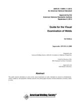

AWS B1.11M/B1.11:2015 Guide for the Visual Examination of Welds
AWS B1.11M/B1.11:2015 3rd Edition guide covers visual weld examination, discontinuities, personnel qualification, weld gauges and inspection equipment.
Wrong edition, wrong file, or a file that won’t open? We replace or refund — contact us within 7 days.
Buy now is for one copy. Buying for a team? Get a quote
About this publication
Product Description
AWS B1.11M/B1.11:2015, Guide for the Visual Examination of Welds, Third Edition, provides practical guidance for personnel who visually examine weldments before, during and after welding.
Prepared by the American Welding Society B1 Committee on Methods of Inspection, the guide introduces the fundamentals of visual examination, personnel qualification, weld surface conditions, examination equipment and documentation.
Current Third Edition
The 2015 Third Edition remains the current AWS B1.11 publication and supersedes AWS B1.11:2000.
The American National Standards Institute approved the Third Edition on September 8, 2014, and the publication carries a 2015 AWS copyright and edition designation.
Purpose of the Guide
AWS developed B1.11 as a tutorial source of basic information concerning visual examination of welds.
The guide is intended for engineers, designers, educators, inspectors, welders, supervisors and other welding personnel who require an understanding of visual examination practices and weld surface conditions.
Visual Examination as an NDE Method
The guide treats visual examination, commonly identified as VT, as a nondestructive examination method in which a weldment, adjacent base metal and various stages of welding are evaluated through direct or aided visual observation.
Gauges, measuring devices and optical aids supplement eyesight but do not replace the fundamental visual examination method.
Not an Acceptance Code
AWS B1.11 is an instructive guide rather than a construction code establishing universal weld acceptance limits.
The applicable welding code, specification, drawing and contract requirements take precedence and determine whether a particular weld condition is acceptable or rejectable.
When Visual Examination Is Performed
The guide divides visual examination into three principal stages:
- prior to welding;
- during welding;
- after welding.
Effective inspection can begin before the arc is struck and continue throughout production rather than being limited to examination of the finished weld.
Clause 1 — General
Clause 1 establishes application, scope and safety and health considerations.
The guide applies to individuals examining welds during any stage of fabrication, including welders, examiners, engineers and supervisors.
Visual Acceptance Criteria
AWS emphasizes that visual acceptance criteria should be clearly established before welding begins.
Defining the applicable requirements in advance allows visual examination to determine whether the completed weldment conforms to approved contract documents rather than relying on subjective judgment after fabrication.
Clause 2 — Normative References
Clause 2 identifies normative references supporting use of the guide.
These referenced documents provide terminology, qualification or other requirements needed when visual examination is performed under a formal welding quality program.
Clause 3 — Qualification of Examination Personnel
Clause 3 addresses qualification of personnel performing visual examination.
The subjects include general qualification requirements, visual acuity, equipment, experience and training, examination procedures and certification programs.
Visual Acuity
Visual examination depends directly on the examiner's ability to observe surface conditions and dimensional features.
The guide therefore addresses visual acuity as a fundamental personnel qualification consideration.
Experience and Training
Visual inspectors require sufficient experience and training to recognize weld conditions and properly use inspection tools.
Knowledge of welding processes, joint configurations, discontinuity terminology and applicable acceptance requirements improves the reliability of visual examination.
Certification Programs
The guide recognizes that personnel certification can be required by the applicable welding standard, contract or legal authority.
AWS QC1 certification may be acceptable in applications where another certification system has not been specifically required.
Clause 4 — Fundamentals of Visual Examination
Clause 4 covers the basic methods and sequence of visual examination.
The section is organized around examination before welding, examination during welding and examination after welding.
Examination Prior to Welding
Preweld examination provides an opportunity to identify conditions that could compromise the finished joint before corrective work becomes expensive.
Typical considerations include material condition, joint preparation, alignment, fit-up, dimensional requirements, cleanliness and accessibility for welding and inspection.
Joint Fit-up and Mismatch
The guide illustrates weld joint mismatch and other dimensional conditions that can be identified before welding begins.
Incorrect alignment or joint preparation can affect penetration, fusion, weld size and final dimensional compliance.
Examination During Welding
In-process visual examination allows inspectors and welding personnel to monitor conditions while the weld is being produced.
Observations during welding can identify problems with technique, joint progression, interpass cleaning, weld profile or other conditions before they become incorporated into the completed weld.
Examination After Welding
Postweld visual examination evaluates the finished weld and surrounding base material.
The inspector can evaluate dimensions, surface profile and visible discontinuities against the acceptance requirements specified by the applicable governing document.
Clause 5 — Weld Surface Conditions
Clause 5 provides extensive treatment of weld surface conditions and the terminology used to describe them.
Technical illustrations and photographs assist users in recognizing commonly encountered welding discontinuities and surface features.
Porosity
The guide illustrates several forms of porosity including scattered, aligned, elongated and piping porosity.
Porosity consists of cavities associated with gas entrapment in weld metal. Whether a particular indication is acceptable depends on the governing acceptance standard.
Incomplete Fusion
Incomplete fusion occurs when fusion does not occur between weld metal and the base metal or between adjacent weld beads.
The guide illustrates several locations in which incomplete fusion can occur so inspectors can distinguish it from other weld conditions.
Incomplete Joint Penetration
Incomplete joint penetration occurs when weld metal does not extend through the joint thickness as required by the joint design.
The publication includes illustrations of incomplete penetration in different joint configurations.
Undercut
Undercut is a groove melted into the base metal adjacent to the weld toe or weld root and left unfilled by weld metal.
Visual examination can be used to identify and measure undercut where the surface is accessible.
Underfill
Underfill describes a weld surface or root condition in which the weld face or root surface extends below the adjacent base-metal surface.
The guide includes examples showing underfill in completed welds.
Overlap
Overlap occurs when weld metal extends beyond the weld toe or root without fusion to the adjacent base metal.
The condition is visually recognizable and is illustrated in the guide using representative weld examples.
Laminations
Laminations are planar separations within base material that can become visible at cut edges or during fabrication.
The guide includes examples to help inspectors distinguish base-metal laminations from weld-related discontinuities.
Seams and Laps
The surface-condition section also addresses seams and laps associated with base-metal manufacturing or processing.
Recognition of these conditions helps prevent an inspector from incorrectly attributing every observed surface indication to welding.
Cracks
The guide provides extensive visual examples of cracking.
Illustrated conditions include longitudinal cracks, transverse cracks, throat cracks, crater cracks, toe cracks and underbead cracking.
Crack location and orientation are important descriptive characteristics when documenting inspection findings.
Slag Inclusions
The guide illustrates slag inclusions and discusses their visual appearance where they intersect an accessible surface.
Subsurface slag generally requires an appropriate volumetric examination method where detection beyond visual examination is necessary.
Weld Reinforcement
Weld reinforcement is weld metal extending above the surface of the base metal or beyond the surface expected from the joint design.
Visual inspection and dimensional measurement can be used to compare reinforcement with the limits established by the governing specification.
Concavity and Convexity
The guide illustrates both concave and convex fillet-weld profiles.
The significance of weld contour depends on weld size, effective throat and the applicable acceptance requirements.
Arc Strikes
Arc strikes occur when the welding arc is initiated outside the intended weld area.
Visual examination can identify surface evidence of unintended arc contact so the condition can be evaluated under the applicable fabrication requirements.
Spatter
Spatter consists of small particles of molten metal expelled during welding and deposited on nearby surfaces.
Its significance depends on workmanship, service and project requirements.
Melt-through
The guide includes visual examples of melt-through at the root side of welded joints.
Inspectors should distinguish intentional root reinforcement or melt-through from conditions that exceed the requirements of the joint design or acceptance standard.
Weld Size
Visual examination frequently includes measurement of weld size.
Fillet-weld leg dimensions, effective profile and other dimensional characteristics can be checked using suitable weld gauges and measuring tools.
Surface Oxidation
The guide includes surface oxidation among the weld conditions considered during visual examination.
One illustrated example shows oxidation associated with insufficient shielding during gas tungsten arc welding.
Clause 6 — Examination Equipment
Clause 6 discusses equipment commonly used to supplement visual examination.
Subjects include equipment calibration and handling, linear measuring devices, temperature measuring devices, weld gauges, optical equipment, ferrite gauges, lighting and electrical meters.
Calibration and Handling
Inspection equipment must be suitable for its intended purpose and maintained appropriately.
Calibration and careful handling improve confidence that dimensional or process-related measurements used during inspection are meaningful.
Linear Measuring Devices
Linear measuring devices are used for checking dimensions such as weld length, spacing, joint dimensions and component alignment.
Appropriate resolution should be selected for the tolerance or feature being inspected.
Temperature Measuring Devices
The guide illustrates temperature-sensitive crayons, contact thermometers and electrical thermocouples.
These tools can support verification of preheat, interpass or other temperature requirements imposed by the welding procedure or governing code.
Weld Gauges
AWS B1.11 includes examples of gauges used to evaluate fillet weld contour, weld dimensions, mismatch and undercut.
Illustrated tools include multipurpose gauges, taper gauges, Hi-Lo mismatch gauges and undercut gauges.
Fiberscopes and Borescopes
Fiberscopes and borescopes can extend visual examination into areas that cannot be viewed directly.
These optical devices can be useful for internal surfaces, confined geometry and other inaccessible weld locations.
Ferrite Gauges
The equipment section includes ferrite gauges used in applicable stainless steel weld-metal evaluation.
Such measurements supplement visual examination where ferrite content forms part of the fabrication or quality-control requirements.
Light Sources
Adequate illumination is fundamental to effective visual examination.
The guide discusses light sources as inspection aids because poor lighting can prevent detection of otherwise visible surface conditions.
Electrical Meters
The publication includes examples of voltage and current measuring equipment used to evaluate welding process parameters.
Illustrated equipment includes voltmeter arrangements and tong-test ammeters.
Clause 7 — Records
Clause 7 addresses records of visual examination.
Documentation allows inspection results, observations and disposition of identified conditions to be retained as part of the fabrication quality record.
Sample Visual Examination Form
An informative annex provides a sample visual examination form.
The example can assist organizations developing consistent inspection records for their own quality-control systems.
Annex A — Common Welding Standards
Annex A provides a list of standards commonly used in the welding industry.
The list helps users identify other documents that can provide detailed design, fabrication, qualification and acceptance requirements beyond the introductory guidance contained in B1.11.
Annex B — Technical Inquiries
Annex B provides guidance for preparing technical inquiries concerning AWS standards.
Formal inquiries are useful when an AWS requirement requires interpretation beyond ordinary application of the published text.
Annex C — Sample Forms
Annex C contains sample forms supporting visual examination documentation.
Organizations can adapt these examples to their own inspection and quality-management systems.
Annex D — Informative References
Annex D provides informative references for users who require additional technical detail concerning visual examination and welding inspection.
Relationship to AWS B1.10
AWS B1.10M/B1.10, Guide for the Nondestructive Examination of Welds, provides broader information on nondestructive examination methods beyond visual examination.
B1.11 focuses specifically on visual examination, while B1.10 discusses visual, liquid penetrant, magnetic particle, radiographic, ultrasonic and other NDE methods.
Relationship to the AWS Welding Inspection Handbook
The AWS Welding Inspection Handbook provides broader inspection training material covering metallurgy, destructive testing, NDE and qualification.
AWS B1.11 is the more focused guide devoted specifically to practical visual examination of welds.
Relationship to AWS A3.0
The terminology used throughout the guide is based on AWS A3.0 welding terminology.
Using standardized terminology helps engineers, inspectors, welders and contractors communicate observed conditions consistently.
Current Amendment and Errata Status
Current ANSI catalog information lists no amendments or corrections for AWS B1.11M/B1.11:2015.
The Third Edition therefore remains the current published revision without a separate AMD or errata designation as of October 2026.
Who Should Use AWS B1.11M/B1.11:2015
- AWS Certified Welding Inspectors;
- welding inspectors and examiners;
- welding engineers;
- quality assurance and quality control personnel;
- welding supervisors;
- welders and welding operators;
- fabrication managers;
- NDE personnel;
- structural and mechanical engineers;
- technical educators and students;
- CWI candidates;
- contractors and fabrication companies.
Product Features
- current Third Edition of AWS B1.11;
- ANSI approved;
- 64 pages in current complete-publication catalog metadata;
- print ISBN 978-0-87171-858-7;
- covers examination before, during and after welding;
- covers qualification of examination personnel;
- addresses visual acuity, training and certification;
- covers weld surface conditions and discontinuity terminology;
- illustrates porosity, incomplete fusion and incomplete penetration;
- illustrates undercut, underfill and overlap;
- covers cracks, slag inclusions and weld reinforcement;
- covers concavity, convexity, arc strikes and spatter;
- covers melt-through, weld size and surface oxidation;
- covers weld gauges and measuring devices;
- covers temperature-measuring equipment;
- covers fiberscopes and borescopes;
- covers ferrite gauges, lighting and electrical meters;
- includes visual examination record guidance;
- includes sample forms and informative references;
- supersedes AWS B1.11:2000.
Product Details
- Standard: AWS B1.11M/B1.11:2015
- Title: Guide for the Visual Examination of Welds
- Edition: Third Edition
- Publisher: American Welding Society
- Publication Year: 2015
- ANSI Approval: September 8, 2014
- Print ISBN: 978-0-87171-858-7
- AWS Order Code: B1.11
- Page Count: 64
- Previous Edition: AWS B1.11:2000
- Current Amendments/Corrections: None listed as of October 2026
- Prepared By: AWS B1 Committee on Methods of Inspection
- Subcommittee: AWS B1B Subcommittee on Visual Examination of Welds
- Language: English
- Publication Type: Welding Inspection Guide
Edition Status Note
AWS B1.11M/B1.11:2015 remains the current Third Edition as of October 2026 and supersedes AWS B1.11:2000. The guide provides visual-examination methods, terminology, equipment guidance and examples but does not replace the acceptance criteria of the applicable construction code, specification or contract. Current ANSI records list no amendments or corrections.